Wenzel Associates employs several in-house systems for measuring phase noise, including our new Model 501-12922B that features superior noise performance:
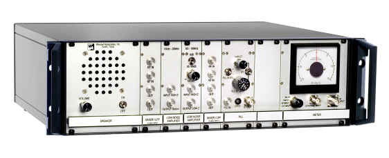
click on image for higher resolution
The measurement technique compares the phase of an oscillator under test to a reference oscillator with similar or superior noise performance. An ordinary PLL holds the relative phase of the two oscillators at quadrature so that small phase variations convert into voltage variations at the output of the mixer. Although the PLL is constantly working to eliminate these phase variations, the time constant is set long enough to preserve the slowest phase variations of interest. The mixer output is connected through a low pass filter to block the RF frequencies to a phase lock amplifier and to a signal analyzer. The signal analyzer gives the power spectral density of the audio noise which is easily converted to phase noise by dividing by the phase slope of the mixer (volts/radian).
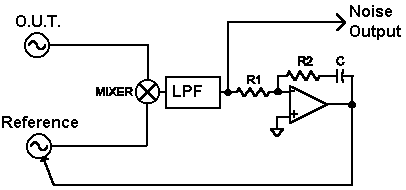
The phase slope of the mixer may be determined in a number of ways including the observation of a beat-note on the oscilloscope or applying a known frequency modulation to the reference oscillator.
The noise output from the mixer can be quite low requiring amplification before spectrum analysis. Our custom amplifier exhibits less than 1nV/root-Hz down to 10 Hz and our custom mixers exhibit similar performance with phase slopes near 1 volt/radian or greater.
An early engineer’s setup is shown below:
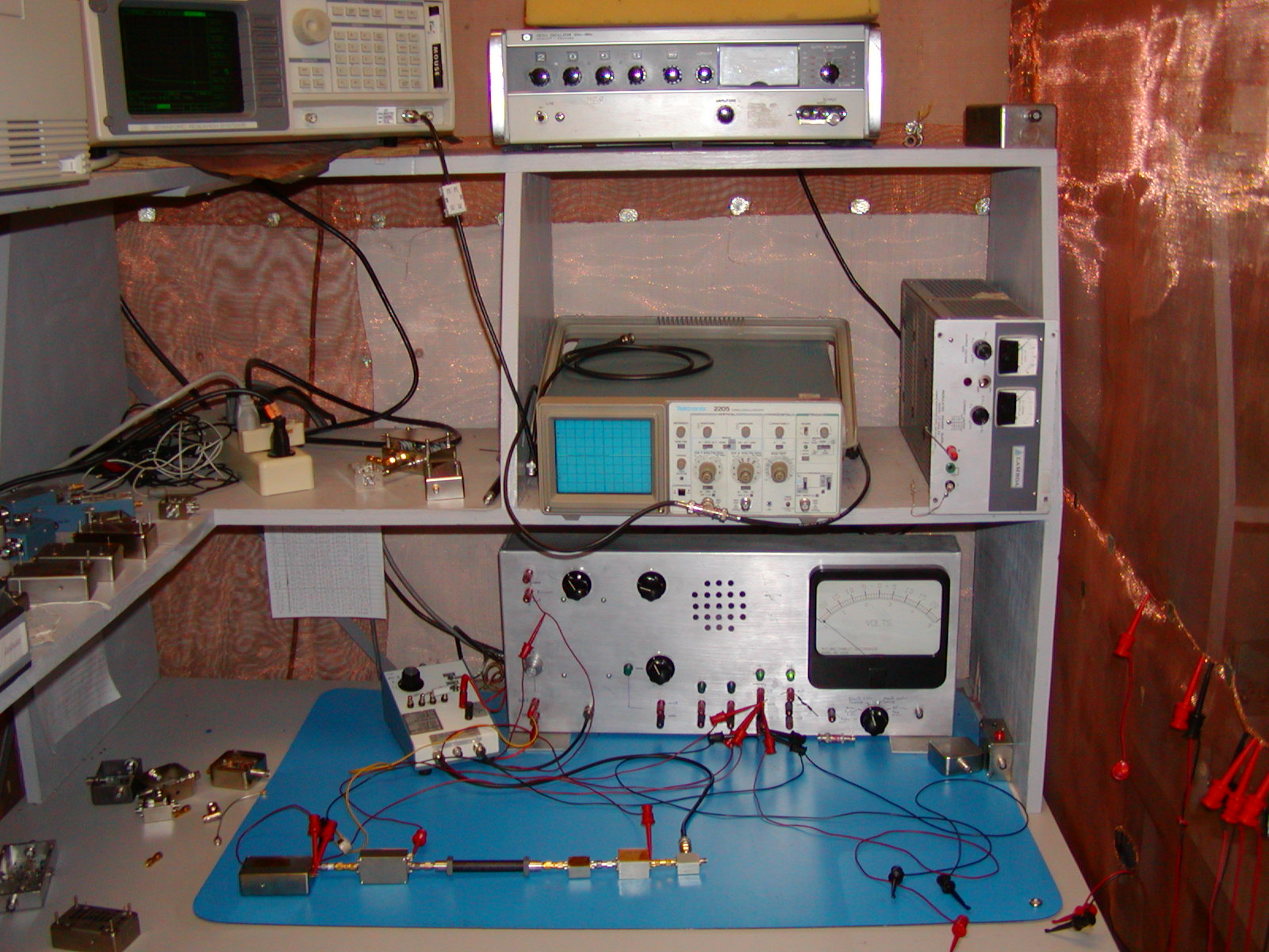
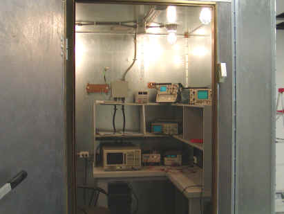
This bench features a low-noise amplifier/PLL (white box bottom left) with easily changed loop components. A backboard includes special low noise power supplies, a multi-purpose meter, electrical tuning gain potentiometer, and a troubleshooting audio amplifier/speaker. A reference oscillator and multiplier chain is on one side of the mixer and the other side awaits a source to be measured. The analyzer is on the high shelf above to keep the noisy monitor away from the oscillators. The power supply features shielded transformers located on the floor to keep magnetic fields away from the oscillators. When better screening is desired, the designer can retreat to one of the “caves”:
Another production system successfully incorporates the power supply into the chassis with the amplifiers:
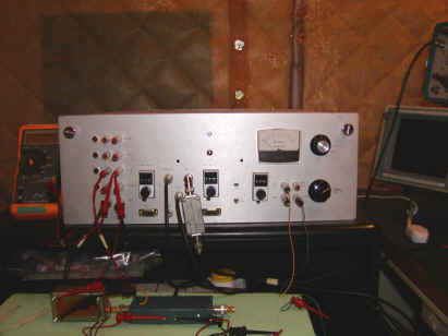
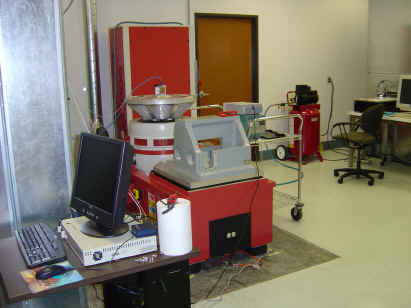
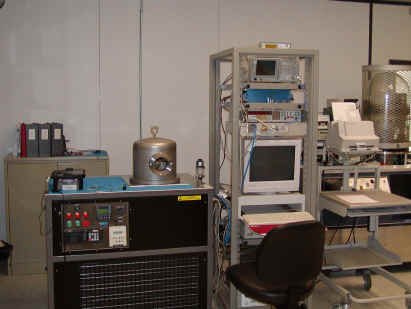
Special power transformers and careful grounding virtually eliminates line-related spurs. Special setups are often required to test phase noise under various environmental conditions including temperature, vibration and even high vacuum for space simulation (two systems below).
A new vibration system allows the testing of large assemblies or instruments. The photo below shows a tiny oscillator mounted on the vertical test table and a special fixture on the slip table.
