The output level of an oscillator is usually specified as an RMS voltage into a particular load or as a power level, typically stated in dBm (dB relative to 1 mW). Output levels are typically below 20 dBm (100mW) but output levels of several watts are available. Logic-level outputs are also common and are usually specified by calling for compatibility with a particular logic family.
Many oscillators are guaranteed to supply a specific level when loaded by a certain impedance (typically 50 ohms). This specification does not necessarily guarantee that the oscillator output will exhibit any particular source impedance, however. The output impedance can be important when the oscillator is driving a passive power splitter since the splitter’s isolation usually depends upon a specific source impedance. Mixers, multipliers and similar non-linear devices can behave in unpredictable ways when driven by reactive or mismatched sources. For example, a high-order step-recovery diode multiplier might reflect a small amount of energy at a phase determined by the trigger point. If this reflected energy bounces back from the oscillator, the combined signal from the oscillator can trigger the diode at a slightly different point generating another, more-shifted reflection. The result can be a “motor-boating”, sawtooth instability which causes sidebands around the desired signal. An oscillator with the same impedance as the cable will absorb the troublesome reflections.
Low frequency oscillators may behave more like a voltage source than a matched source. For example, the standard low-frequency Small Fry and Timekeeper oscillators have a near zero ohm output impedance delivering 1 volt RMS. The low impedance means that reasonably good isolation between two loads may be achieved simply by connecting the loads to the oscillator though 50 ohm resistors. The low-Z output is also more efficient since no power is dissipated in an internal resistor.
VHF and higher frequency oscillators should be specified to have reasonably good return loss (10 dB or better). A 10 dB return loss means that the reflected signal will be 10 dB below the incident signal. A common specification is 14 dB which is a VSWR of 1.5. See the loss chart.
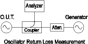
Return loss is a popular way to specify the output impedance since it is easily measured. A signal near the oscillator’s frequency is applied to the oscillator through a directional coupler or isolator. If the oscillator exhibits the desired output impedance then very little signal will return back through the coupler (high return loss) . The dB difference between the test signal and the reflected signal is the return loss (after correcting for the coupler’s loss).
