Phase noise may seem a bit mysterious to the uninitiated but any engineer familiar with “ordinary” noise and “ordinary” power spectral density can be brought up to speed rather quickly. The output of an oscillator may be represented by a phasor diagram.

The signal is represented by a vector with a length proportional to the signal amplitude rotating about the origin at the oscillator’s frequency. At the tip of this vector is a little, randomly directed vector which represents the oscillator’s noise. This noise vector may be represented by two orthogonal vectors, one pointing in the direction of the signal vector and one pointing in the direction of the rotation. The amplitude vector is the familiar amplitude noise and the other vector is the phase noise vector. Obviously when the amplitude vector changes, the oscillator’s overall amplitude changes and when the phase noise vector changes, the oscillator’s phase changes. Although it is intuitive to compare amplitude jitter to the overall amplitude, it may seem arbitrary to compare the phase jitter in radians to the amplitude of the carrier – the two quantities seem unrelated. The confusion rests at the feet of the small angle assumption which states that the sine of a small angle is equal to the angle. When phase noise is measured, it is small variations in the phase angle that are measured and then the length of the phase noise vector is inferred. The small angle assumption states that the length of the phase noise vector is equal to the measured angle multiplied by the signal size. Or stated differently, the measured angle is the phase noise vector divided by the signal size. (For reasonably good oscillators the noise angle is quite small.) Notice that if the little noise vector is independent from the oscillator level (additive noise) then a larger oscillator level will give lower phase noise just as the AM signal to noise level would improve. If the phase variations are a modulation of the phase then the little vector will grow with the signal vector keeping the angle constant just as an AM modulated noise sideband will grow with the carrier size.
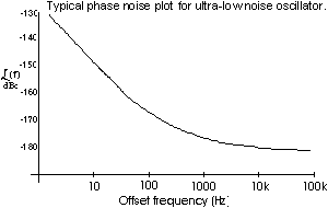
When observed on a spectrum analyzer, amplitude and phase noise will appear as sideband noise on both sides of the carrier. Often, phase noise specifications refer to single-sideband noise denoted by a script L (see chart below). Most phase noise measurement schemes fold both sidebands together the way that a simple AM detector combines both AM sidebands and, consequently, the measured noise will be about 3 dB higher than the single-sideband noise depending on the degree of coherency of the sidebands. (Script L(f) has been recently redefined as equal to one half the sum of both sidebands thus avoiding the whole issue of the coherency of the two sidebands.)
Measuring the noise angle or, more precisely, the spectral density of the noise angle is conceptually simple. The oscillator to be measured is phase-locked to a reference oscillator using a long time-constant (slow loop response). Variations in the phase of the oscillator under test will cause variations in the voltage at the output of the mixer. A conversion factor may be determined for the mixer/ phase detector by observing the slope of the beat-note at zero volts when the oscillators are not locked (as X volts per radian). The spectral density of the noise voltage is then measured (with the oscillators locked together) using ordinary techniques including FFT analyzers or Wave analyzers. Several complications will arise, especially when measuring oscillators exhibiting noise as good as the reference noise. Many publications are available detailing the pitfalls of phase noise measurements including several from NIST.

The harmonic content in the output of an oscillator is usually of little importance and levels better than 30dB below the fundamental are readily achieved. Much higher attenuation of harmonics may be achieved when a particular harmonic falls on a critical frequency as in a sensitive receiver but care must be taken to avoid the re-generation of the undesired harmonic when the oscillator signal is processed by the designer’s circuitry.
Sub-harmonics are present at some level when the output of the oscillator is multiplied from a lower frequency crystal oscillator. The term sub-harmonic should be clearly defined in the specification since a final output frequency may be achieved with different crystal frequencies and multiplication factors.
Wenzel Associates manufacturers extremely low phase noise oscillators as confirmed by NIST calibration reports which are available for viewing with the Adobe Acrobat viewer for 5 MHz oscillators and 100MHz oscillators.
Also see: